Federal Aviation Regulations
Appendix A to Part 23 — Simplified Design Load Criteria
A23.1 General.(a) The design load criteria in this appendix are an approved equivalent of those in §§23.321 through 23.459 of this subchapter for an airplane having a maximum weight of 6,000 pounds or less and the following configuration:
(1) A single engine excluding turbine powerplants;
(2) A main wing located closer to the airplane's center of gravity than to the aft, fuselage-mounted, empennage;
(3) A main wing that contains a quarter-chord sweep angle of not more than 15 degrees fore or aft;
(4) A main wing that is equipped with trailing-edge controls (ailerons or flaps, or both);
(5) A main wing aspect ratio not greater than 7;
(6) A horizontal tail aspect ratio not greater than 4;
(7) A horizontal tail volume coefficient not less than 0.34;
(8) A vertical tail aspect ratio not greater than 2;
(9) A vertical tail platform area not greater than 10 percent of the wing platform area; and
(10) Symmetrical airfoils must be used in both the horizontal and vertical tail designs.
(b) Appendix A criteria may not be used on any airplane configuration that contains any of the following design features:
(1) Canard, tandem-wing, close-coupled, or tailless arrangements of the lifting surfaces;
(2) Biplane or multiplane wing arrangements;
(3) T-tail, V-tail, or cruciform-tail (+) arrangements;
(4) Highly-swept wing platform (more than 15-degrees of sweep at the quarter-chord), delta planforms, or slatted lifting surfaces; or
(5) Winglets or other wing tip devices, or outboard fins.
A23.3 Special symbols.
n
n
n
n
n
A23.5 Certification in more than one category.
The criteria in this appendix may be used for certification in the normal, utility, and acrobatic categories, or in any combination of these categories. If certification in more than one category is desired, the design category weights must be selected to make the term n
A23.7 Flight loads.
(a) Each flight load may be considered independent of altitude and, except for the local supporting structure for dead weight items, only the maximum design weight conditions must be investigated.
(b) Table 1 and figures 3 and 4 of this appendix must be used to determine values of n
(c) Figures 1 and 2 of this appendix must be used to determine values of n
(d) Each specified wing and tail loading is independent of the center of gravity range. The applicant, however, must select a c.g. range, and the basic fuselage structure must be investigated for the most adverse dead weight loading conditions for the c.g. range selected.
(e) The following loads and loading conditions are the minimums for which strength must be provided in the structure:
(1) Airplane equilibrium. The aerodynamic wing loads may be considered to act normal to the relative wind, and to have a magnitude of 1.05 times the airplane normal loads (as determined from paragraphs A23.9 (b) and (c) of this appendix) for the positive flight conditions and a magnitude equal to the airplane normal loads for the negative conditions. Each chordwise and normal component of this wing load must be considered.
(2) Minimum design airspeeds. The minimum design airspeeds may be chosen by the applicant except that they may not be less than the minimum speeds found by using figure 3 of this appendix. In addition, V
(3) Flight load factor. The limit flight load factors specified in Table 1 of this appendix represent the ratio of the aerodynamic force component (acting normal to the assumed longitudinal axis of the airplane) to the weight of the airplane. A positive flight load factor is an aerodynamic force acting upward, with respect to the airplane.
A23.9 Flight conditions.
(a) General. Each design condition in paragraphs (b) and (c) of this section must be used to assure sufficient strength for each condition of speed and load factor on or within the boundary of a V−n diagram for the airplane similar to the diagram in figure 4 of this appendix. This diagram must also be used to determine the airplane structural operating limitations as specified in §§23.1501(c) through 23.1513 and §23.1519.
(b) Symmetrical flight conditions. The airplane must be designed for symmetrical flight conditions as follows:
(1) The airplane must be designed for at least the four basic flight conditions, “A”, “D”, “E”, and “G” as noted on the flight envelope of figure 4 of this appendix. In addition, the following requirements apply:
(i) The design limit flight load factors corresponding to conditions “D” and “E” of figure 4 must be at least as great as those specified in Table 1 and figure 4 of this appendix, and the design speed for these conditions must be at least equal to the value of V
(ii) For conditions “A” and “G” of figure 4, the load factors must correspond to those specified in Table 1 of this appendix, and the design speeds must be computed using these load factors with the maximum static lift coefficient C
(iii) Conditions “C” and “F” of figure 4 need only be investigated when n
(2) If flaps or other high lift devices intended for use at the relatively low airspeed of approach, landing, and takeoff, are installed, the airplane must be designed for the two flight conditions corresponding to the values of limit flap-down factors specified in Table 1 of this appendix with the flaps fully extended at not less than the design flap speed V
(c) Unsymmetrical flight conditions. Each affected structure must be designed for unsymmetrical loadings as follows:
(1) The aft fuselage-to-wing attachment must be designed for the critical vertical surface load determined in accordance with paragraph SA23.11(c)(1) and (2) of this appendix.
(2) The wing and wing carry-through structures must be designed for 100 percent of condition “A” loading on one side of the plane of symmetry and 70 percent on the opposite side for certification in the normal and utility categories, or 60 percent on the opposite side for certification in the acrobatic category.
(3) The wing and wing carry-through structures must be designed for the loads resulting from a combination of 75 percent of the positive maneuvering wing loading on both sides of the plane of symmetry and the maximum wing torsion resulting from aileron displacement. The effect of aileron displacement on wing torsion at V
(i) Cm=Cm +0.01δμ(up aileron side) wing basic airfoil.
(ii) Cm=Cm −0.01δμ(down aileron side) wing basic airfoil, whereδμis the up aileron deflection andδd is the down aileron deflection.
(4) Δ critical, which is the sum ofδμ+δd must be computed as follows:
(i) Compute Δα and Δ
Where Δ
(ii) Compute K from the formula:
whereδαis the down aileron deflection corresponding toΔα,andδb is the down aileron deflection corresponding toΔb as computed in step (i).
(iii) If K is less than 1.0,Δαis Δ critical and must be used to determineδ
(iv) If K is equal to or greater than 1.0,Δ
(d) Supplementary conditions; rear lift truss; engine torque; side load on engine mount. Each of the following supplementary conditions must be investigated:
(1) In designing the rear lift truss, the special condition specified in §23.369 may be investigated instead of condition “G” of figure 4 of this appendix. If this is done, and if certification in more than one category is desired, the value of W/S used in the formula appearing in §23.369 must be that for the category corresponding to the maximum gross weight.
(2) Each engine mount and its supporting structures must be designed for the maximum limit torque corresponding to METO power and propeller speed acting simultaneously with the limit loads resulting from the maximum positive maneuvering flight load factor n
(3) Each engine mount and its supporting structure must be designed for the loads resulting from a lateral limit load factor of not less than 1.47 for the normal and utility categories, or 2.0 for the acrobatic category.
A23.11 Control surface loads.
(a) General. Each control surface load must be determined using the criteria of paragraph (b) of this section and must lie within the simplified loadings of paragraph (c) of this section.
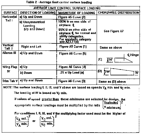
(b) Limit pilot forces. In each control surface loading condition described in paragraphs (c) through (e) of this section, the airloads on the movable surfaces and the corresponding deflections need not exceed those which could be obtained in flight by employing the maximum limit pilot forces specified in the table in §23.397(b). If the surface loads are limited by these maximum limit pilot forces, the tabs must either be considered to be deflected to their maximum travel in the direction which would assist the pilot or the deflection must correspond to the maximum degree of “out of trim” expected at the speed for the condition under consideration. The tab load, however, need not exceed the value specified in Table 2 of this appendix.
(c) Surface loading conditions. Each surface loading condition must be investigated as follows:
(1) Simplified limit surface loadings for the horizontal tail, vertical tail, aileron, wing flaps, and trim tabs are specified in figures 5 and 6 of this appendix.
(i) The distribution of load along the span of the surface, irrespective of the chordwise load distribution, must be assumed proportional to the total chord, except on horn balance surfaces.
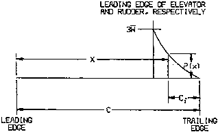
(ii) The load on the stabilizer and elevator, and the load on fin and rudder, must be distributed chordwise as shown in figure 7 of this appendix.
(iii) In order to ensure adequate torsional strength and to account for maneuvers and gusts, the most severe loads must be considered in association with every center of pressure position between the leading edge and the half chord of the mean chord of the surface (stabilizer and elevator, or fin and rudder).
(iv) To ensure adequate strength under high leading edge loads, the most severe stabilizer and fin loads must be further considered as being increased by 50 percent over the leading 10 percent of the chord with the loads aft of this appropriately decreased to retain the same total load.
(v) The most severe elevator and rudder loads should be further considered as being distributed parabolically from three times the mean loading of the surface (stabilizer and elevator, or fin and rudder) at the leading edge of the elevator and rudder, respectively, to zero at the trailing edge according to the equation:
 View or download PDF
Where—
P(x)=local pressure at the chordwise stations x,
c=chord length of the tail surface,
cf=chord length of the elevator and rudder respectively, and
w
(vi) The chordwise loading distribution for ailerons, wing flaps, and trim tabs are specified in Table 2 of this appendix.
(2) If certification in the acrobatic category is desired, the horizontal tail must be investigated for an unsymmetrical load of 100 percent w on one side of the airplane centerline and 50 percent on the other side of the airplane centerline.
(d) Outboard fins. Outboard fins must meet the requirements of §23.445.
(e) Special devices. Special devices must meet the requirements of §23.459.
A23.13 Control system loads.
(a) Primary flight controls and systems. Each primary flight control and system must be designed as follows:
(1) The flight control system and its supporting structure must be designed for loads corresponding to 125 percent of the computed hinge moments of the movable control surface in the conditions prescribed in A23.11 of this appendix. In addition—
(i) The system limit loads need not exceed those that could be produced by the pilot and automatic devices operating the controls; and
(ii) The design must provide a rugged system for service use, including jamming, ground gusts, taxiing downwind, control inertia, and friction.
(2) Acceptable maximum and minimum limit pilot forces for elevator, aileron, and rudder controls are shown in the table in §23.397(b). These pilots loads must be assumed to act at the appropriate control grips or pads as they would under flight conditions, and to be reacted at the attachments of the control system to the control surface horn.
(b) Dual controls. If there are dual controls, the systems must be designed for pilots operating in opposition, using individual pilot loads equal to 75 percent of those obtained in accordance with paragraph (a) of this section, except that individual pilot loads may not be less than the minimum limit pilot forces shown in the table in §23.397(b).
(c) Ground gust conditions. Ground gust conditions must meet the requirements of §23.415.
(d) Secondary controls and systems. Secondary controls and systems must meet the requirements of §23.405.
Table 1—Limit Flight Load Factors
[Limit flight load factors]
| Flight load factors | Normal category | Utility category | Acrobatic category |
|---|---|---|---|
| Flaps up: | |||
| n 1 | 3.8 | 4.4 | 6.0 |
| n 2 | −0.5 n 1 | ||
| n 3 | (1) | ||
| n 4 | (2) | ||
| Flaps down: | |||
| n flap | 0.5 n 1 | ||
| n flap | 3Zero |
1Find n 3from Fig. 1
2Find n 4from Fig. 2
3Vertical wing load may be assumed equal to zero and only the flap part of the wing need be checked for this condition.
 View or download PDF
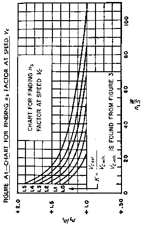 View or download PDF
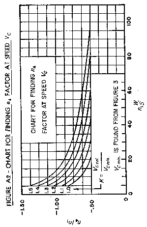 View or download PDF
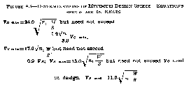 View or download PDF
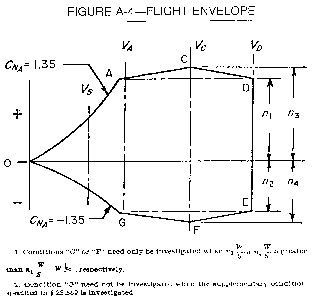 View or download PDF
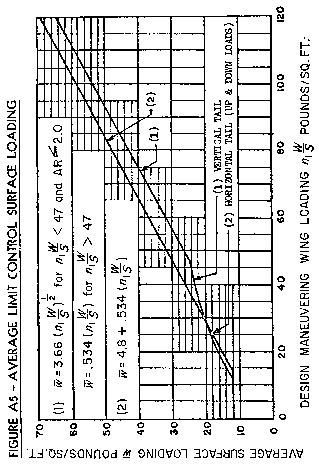 View or download PDF
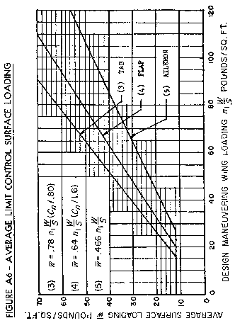 View or download PDF
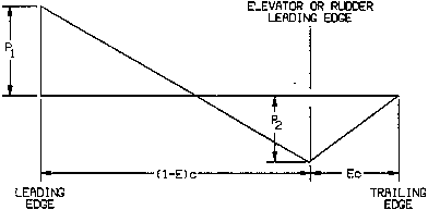 View or download PDF
where:
w
E=ratio of elevator (or rudder) chord to total stabilizer and elevator (or fin and rudder) chord.
d′=ratio of distance of center of pressure of a unit spanwise length of combined stabilizer and elevator (or fin and rudder) measured from stabilizer (or fin) leading edge to the local chord. Sign convention is positive when center of pressure is behind leading edge.
c=local chord.
Note: Positive values of w
[Doc. No. 4080, 29 FR 17955, Dec. 18, 1964, as amended by Amdt. 23–7, 34 FR 13097, Aug. 13, 1969; 34 FR 14727, Sept. 24, 1969; Amdt. 23–16, 40 FR 2577, Jan. 14, 1975; Amdt. 23–28, 47 FR 13315, Mar. 29, 1982; Amdt. 23–48, 61 FR 5149, Feb. 9, 1996]
NEXT: Appendix A to Part 23 - Simplified Design Load Criteria
PREVIOUS: Sec. 23.1589 - Loading information.